I'll expand on other yokes in the near future when time permits, but for right now I will put this 1st self explanatory pic here as a start. Well...I guess it does need a tad more info :) This is the yoke & it's plug for the Electrohome GO7 chassis connections with color coded break down.
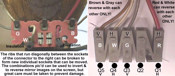
Red & white are the horizontal winding & can be reversed if pic is mirrored & the same for the brown & gray wires which are the vertical winding, but no other color combination can be made without serious damage being done to the monitor in a split second.
You should note that there is a blank post as many a tech has brought in a monitor with horizontal or vertical collapse only to find they have missed a post & used the air post for one of the sockets.
There are a great number of sites where you can find out how to use a switch to flip on the fly, so I won't go into that except to say that I would use 2 separate switches as some games require only the vertical or horizontal to be flipped while the other remains in the same position. I would also make certain to have the red & white connections insulated to prevent hot burning shocks if accidently touched.
UPDATE:
Taking a bit of time today...5/9/00...to expound a bit on this topic, as many have difficulty with flipping their pics when changing games. About 75 percent of other yoke plugs are going to be more straight forward ... some will be gray, and others black, but the wiring code will remain the same as follows: red & blue horizontal winding - green & yellow vertical winding. ALWAYS check with an ohmmeter to be sure that the color code was followed, and that someone has not previously changed wires around. You will get a lower reading on the horizontal winding, and typical ranges are from 2 to 12 ohms on the H winding & from 12 to 60 ohms on the V winding.
The next thing to look for before any changes are made, is a parallel header in the vicinity of the yoke header & plug. Many of the imports from around the world use dual, crisscrossed headers, whereby you can simply unplug the yoke and move it to the adjacent header to reverse images.
Okay. You've checked it all out & know you can't flip the pic with the pcb's dip switching, and you have no alternate header to select, so here is the next easiest, quickest way to invert your image/s. A typical yoke plug will look like this pic ...
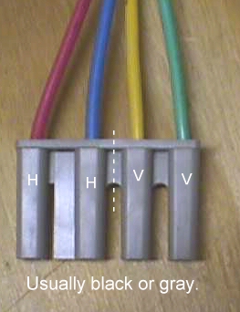
... and if you cut it down the middle, making two separate plugs, you can then reverse either plug giving you the option of changing one or both images; mirror & upside down. Unlike the staggered wiring of the GO7 yoke, other yokes kept the windings' pins side-by-side usually, and with a wider gap/spacing between the H winding pins to prevent you from plugging up to the wrong winding.
Update 3/25/04
Many people still have trouble with the yokes, so I'm going to try to get it a little more basic using laymenese. The pic below shows the yoke as found on a schematic. The looped lines are the electrical symbols for a coil. A coil (inductor) is one of the most basic components in electronics and is nothing more than a piece of wire wrapped into a number of turns on an iron core, wrapped on an insulator (non-conductor) of some sort, or even shellacked into a free form that is self supporting. If you were to take a 20" piece of wire & wrap it onto a pencil in a number turns you'd have a coil. More or less turns & the thickness of the wire will determine the value. The yoke coils adhere to this same simplified principle even though they are intimidating in their huge interwoven bell-like patterns.
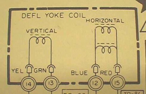
The horizontal coil above is pic'd as two coils in parallel & the vertical coil pic'd as one actually should be pic'd as two in series, but regardless of how many coils are used, you only need view them as two... the horizontal & the vertical. If it helps, slice right down through the block above and push these two coils apart, as they are two entirely separate coils. Standard colors are written in to ID the two coils, but so many times the colors are just whatever the mfr happened to have on hand & this seems to trip a lot of you up when trying to determine which of the 4 wires go where... and you already know you don't want to mix them up! If you take an ohmmeter and measure from position 14 above to position 12 or 15, you can see that your meter is not going to do a thing... open circuit... as it will be from position 13 to either of those 2 positions. The only way you're going to get a reading is by being across two of the positions that represent the two ends of the coiled wire, so it's fairly simple to match up the 2 pair of wires for each coil. If you have "Fruity Pebbles" wire colors on your yoke it would be a good idea to jot down the colors of each pair. Now to flip the pic that you actually see on the screen all you need do is reverse the wire colors in a pair... above vertical winding would be equivalent of taking the wire from 13 & swapping it with the end that is on 14. It's as simple as that & if you want to determine which coil is horizontal & which is vertical, then just read your ohmmeter when you are determining the pair & the larger reading of the two will be the vertical winding, while the one that nearly shows as shorted will be the horizontal winding.
Happy Gaming...........
Help Page Index Big Bear's Bulletin Board Site Index